
DeepSeek V4.1 Flash Engineering, Part 3: Integrating Vision—Finding Differences with Intermediate Tensors
From image_url through the vision tower, aligner, and dual-bias MoE routing: tracing tensor differences while integrating DeepSeek V4.1 Flash vision
Part 2 followed weight assembly into an eight-GPU text pipeline, preserving compressed KV, selections, and mHC state across device boundaries. This article connects images to that same language backbone.
Multimodal integration can create a convincing false positive. The HTTP request succeeds, the vision tower returns without an error, and the model generates text. Yet a one-pixel resize difference, a different RoPE ordering, or an incorrectly padded aligner grid gives every later layer a tensor with the right shape and the wrong meaning.
We therefore did not treat a plausible image description as sufficient evidence. zLLM first connected the end-to-end path, then used the official PyTorch implementation as an oracle and divided the vision pipeline into observable boundaries. The first boundary with a material difference identified where to investigate.
Multimodal basics: turn an image into tokens the language model can process
A language model consumes rows of hidden vectors, while a raw image is a two-dimensional pixel array. A multimodal model first converts both modalities into a shared representation space and then sends them through the same inference path.
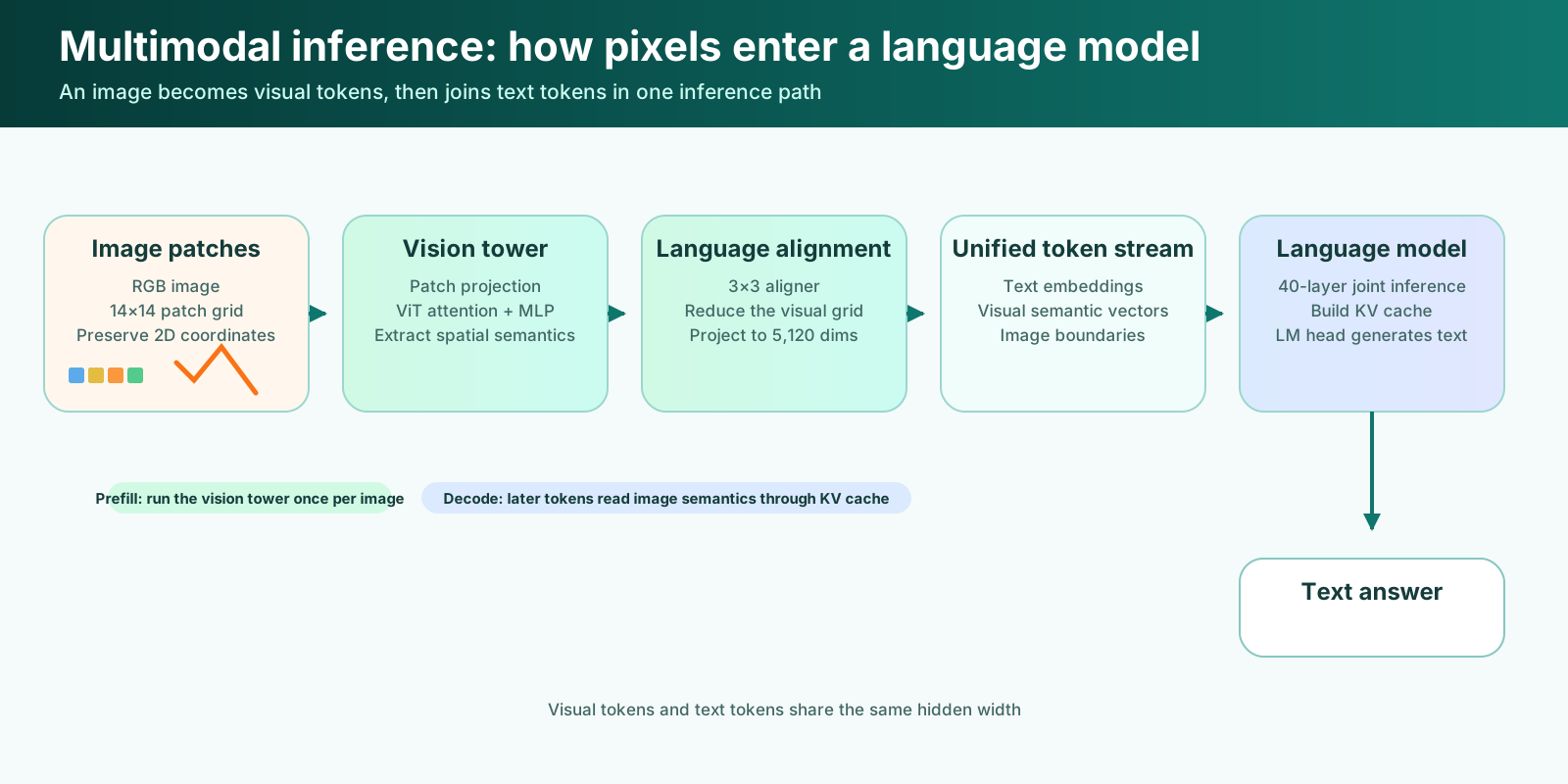
The first step is patching. The image is divided into fixed-size regions; DeepSeek V4.1 Flash, for example, uses 14×14 RGB patches. Each patch becomes one row of numbers while retaining its grid coordinates. A continuous image becomes a sequence of visual tokens with two-dimensional positions:
The second step is vision-tower encoding. A patch projection maps pixel rows into a vision hidden space. ViT attention, positional encoding, and MLPs then give each patch information from the whole image. A small orange region in a carrot image can come to represent shape, object category, neighboring objects, and spatial location as well as local color. The result is not one vector summarizing the entire image, but a set of semantic vectors that preserve spatial structure.
The third step is alignment with the language space. Vision hidden width usually differs from language hidden width, and the patch sequence may be too long. An aligner or merger combines nearby visual positions and projects them to the language model's hidden size. This module is trained with the model. It performs more than reshaping a matrix: it maps visual features into a representation the language model has learned to interpret.
Finally, the model inserts these visual tokens into reserved image positions in the text sequence. Text tokens still come from vocabulary embeddings, while vision vectors replace the image-placeholder rows. The language model now sees one unified hidden sequence:
Language attention lets question tokens read relevant visual tokens and fuses visual information with surrounding text layer by layer. The model still predicts the next text token through its LM head, so image recognition, description, and visual question answering all appear as ordinary text generation at the output.
In an inference engine, the vision tower normally computes image semantics once during prefill. These visual tokens build language-model KV cache together with the rest of the prompt. During token-by-token decode, later tokens read the encoded image context through that cache; the engine does not rerun the full vision tower for every generated token.
DeepSeek V4.1 Flash and Qwen3-VL share this overall design. They differ in patch construction, spatial or temporal positions, grid reduction, and whether visual features enter the language stack once or at multiple depths. With this common principle established, intermediate-tensor comparison has a precise goal: every boundary must preserve the visual meaning and spatial layout used during training.
Connect the complete image-to-text path first
An OpenAI-compatible image_url part passes through much more than a Vision Encoder:
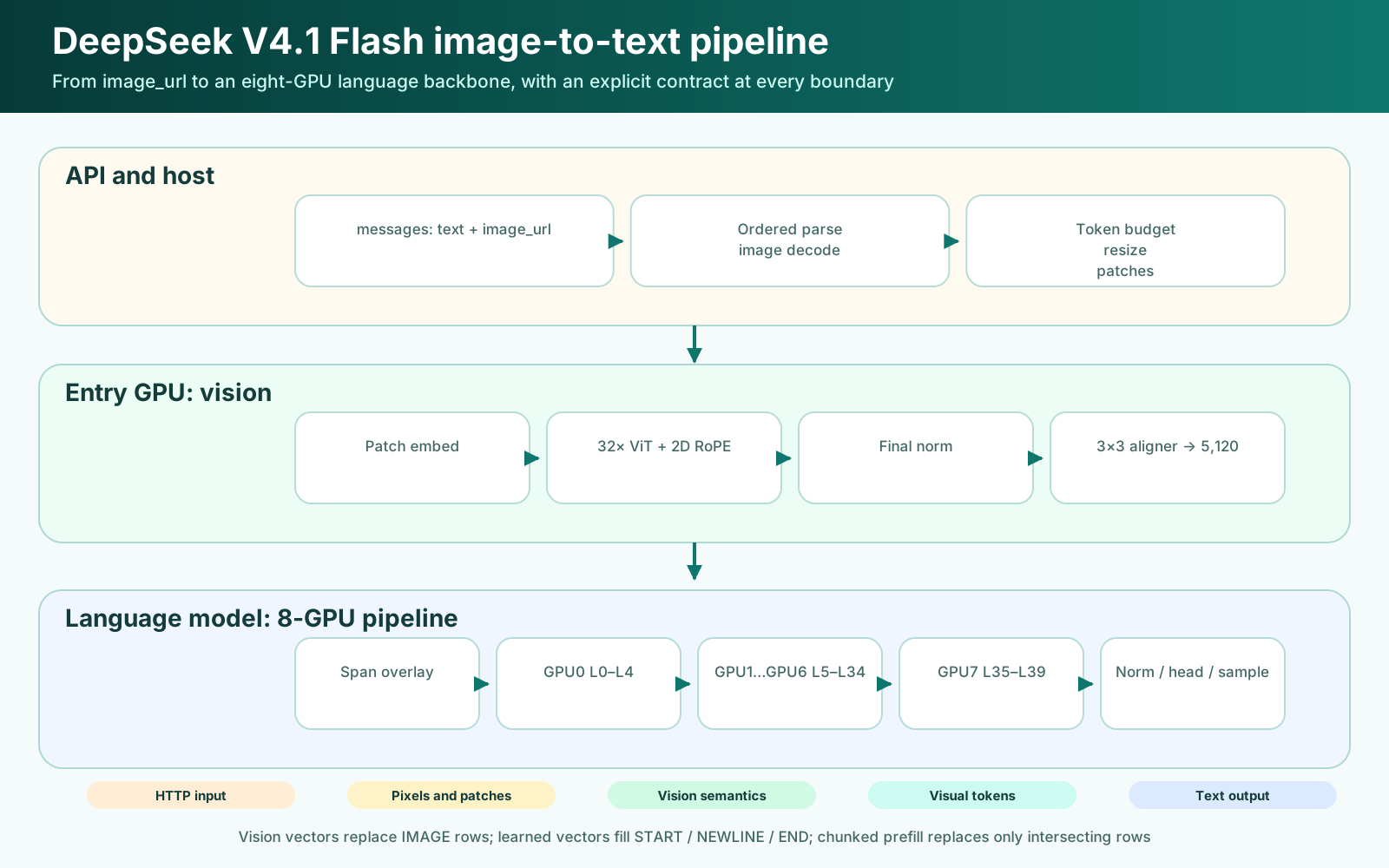
The zLLM node preserves the original order of text and images and writes image placeholders into the prompt. After preprocessing, each placeholder expands into a two-dimensional token span:
[IMAGE_START]
[IMAGE] [IMAGE] ... [IMAGE] [IMAGE_NEWLINE]
[IMAGE] [IMAGE] ... [IMAGE] [IMAGE_NEWLINE]
...
[IMAGE_END]
All these positions carry the same image_token_id in input_ids. Additional type and embedding assembly rules distinguish START, IMAGE, NEWLINE, and END. Aligner output replaces regular IMAGE rows, while learned vectors fill the boundary and newline positions.
This representation must also survive chunked prefill. An image span may cross a chunk boundary, so the engine cannot replace rows only once in a complete prompt. zLLM retains each image's token range and overlay rows. When it assembles an embedding chunk, it replaces only the intersecting part.
Step 1: Reproduce the discrete image-processing rules
V4.1 Flash uses 14×14 patches, a 1,024-dimensional vision hidden state, 16 attention heads, and a 32-layer ViT. The aligner merges a 3×3 spatial neighborhood and projects the result into the language model's 5,120-dimensional hidden state. A single image may use at most 1,024 language tokens, while images below the minimum pixel budget are enlarged proportionally first.
Preprocessing contains a chain of discrete decisions:
- Compute the largest grid that fits the aspect ratio and token budget.
- Constrain target dimensions to the patch and downsampling grid.
- Apply PIL
containsemantics with bicubic resizing. - Center the result on RGB 127 gray padding.
- Flatten patches in
(grid_y, grid_x, channel, y, x)order. - Map pixels from
[0, 255]to[-1, 1].
The first discrepancy appeared in step three. A common contain helper may use ceil to cover a destination edge. The official path branches on aspect ratio, computes the other dimension, and applies round. A one-pixel difference changes padding offsets and boundary patches, after which every corresponding row differs.
zLLM therefore implements this planning and rounding rule explicitly instead of applying a generic resize helper. Image preprocessing is part of the model's numerical definition, even though it occurs before the vision tower.
Step 2: Locate the first divergence with five tensor boundaries
Final generated text cannot tell us whether an error began in preprocessing, visual attention, the aligner, or the language model. We made the official implementation dump intermediate tensors and exported the same boundaries from zLLM:
| Boundary | What it can isolate |
|---|---|
| Patches | Resize, padding, normalization, and patch row order |
| 2D RoPE cos/sin | Height and width coordinates, frequency order, and rotation layout |
| Block 0 output | Patch projection, QKV bias, attention, and residual order |
| Final norm output | Error growth across 32 blocks and RMSNorm semantics |
| Aligner output | Right/bottom padding, 3×3 unfold, channel order, and two linear projections |
The method is useful because it always looks for the earliest material divergence. If patches differ, investigation stops at preprocessing. If patches match and block 0 diverges, positional encoding and the first vision block become the search area. This avoids guessing about an error dozens of layers earlier from final text.
zLLM added optional vision debug dumps and a focused real-weight test for this purpose. It runs only the vision tower and aligner and takes about one second on one GPU, avoiding a full eight-GPU language run for every comparison.
Step 3: Height and width occupy blocks in 2D RoPE
Visual attention uses two-dimensional positions. For a grid coordinate (h, w), the official implementation builds height and width frequencies and flattens them as:
[h·f0, h·f1, ..., h·fn, w·f0, w·f1, ..., w·fn]
Our early implementation interpreted the layout as interleaved:
[h·f0, w·f0, h·f1, w·f1, ...]
The shapes are identical, and basic invariants such as cos² + sin² = 1 pass for both. Each channel nevertheless receives a different spatial coordinate. Comparing cos/sin directly led us to use height and width blocks and to preserve the official half-vector rotation convention.
This shows why tensor comparison reveals more than shape checks. The incorrect ordering causes no out-of-bounds access or NaN; it simply presents another geometry to the model.
Step 4: The aligner pads a two-dimensional grid
After 32 ViT blocks, the aligner pads the right and bottom edges to multiples of three and unfolds each 3×3 window. An early implementation simplified padding to appending zero rows to the flattened tensor.
Appending rows happens to work for bottom padding. It fails on the right edge. If each source row contains five patches and must be padded to six, the sixth position of every row should be zero. Appending zeros only at the end places the first valid patch of the second row in the first row's padding slot, shifting the rest of the image.
The corrected implementation maps each (source_y, source_x) to a 3×3 destination window and an offset inside that window. It also follows the official channel-major unfold order:
[the 9 positions of channel 0,
 the 9 positions of channel 1,
 ...]
The current path downloads final-norm output to the host, assembles this grid, and uploads it again. The transfer is at most about 15 MB per image. This keeps the semantics explicit and easy to compare; moving assembly into a device kernel remains a separate optimization.
Step 5: Pad 588 columns to 592 without changing the math
One 14×14 RGB patch contains:
3 × 14 × 14 = 588
The current ROCm matrix path requires input columns aligned to 16, and 588 is not a multiple of 16. zLLM pads four zeros onto both the patch input and the matching projection-weight rows, extending the operation to 592 columns:
[x0 ... x587, 0, 0, 0, 0]
×
[w0 ... w587, 0, 0, 0, 0]
The new columns always contribute zero to the dot product. The result is mathematically equivalent to the original 588-dimensional linear layer while satisfying the kernel's tile constraint. This adaptation belongs at the backend preparation boundary and does not become a new model dimension.
After correcting contain rounding, RoPE layout, aligner grid assembly, and patch alignment, the recorded maximum relative difference at the aligner was about 5%. We treat that as an error range to continue monitoring on the BF16 execution path, rather than claiming elementwise identity.
Comparing the DeepSeek V4.1 Flash and Qwen3-VL vision towers
zLLM also supports Qwen3-VL. Both models turn dynamically sized images into patches, encode them with a ViT, and project the result into the language hidden state, but their tensor contracts differ substantially. The comparison below uses zLLM's current Qwen3-VL-32B configuration; other sizes and MoE variants in the Qwen3-VL family may use different language-layer specifications.
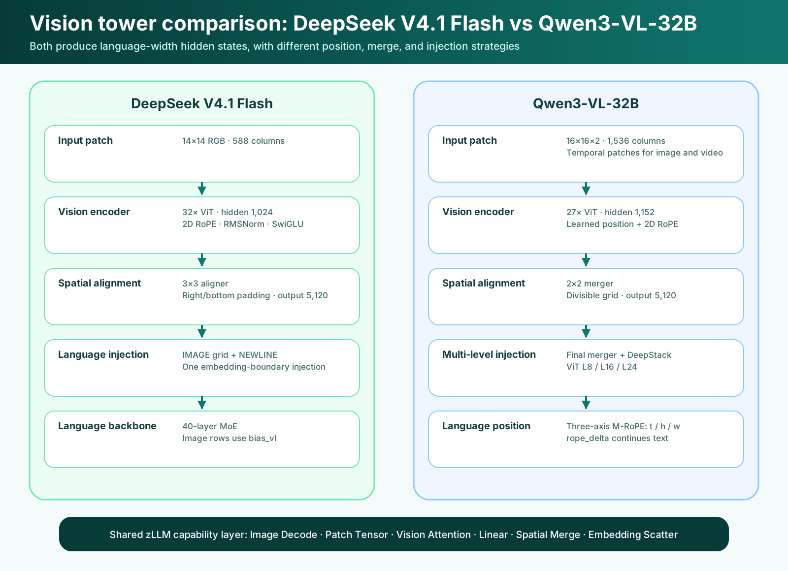
| Stage | DeepSeek V4.1 Flash | Current zLLM Qwen3-VL-32B path |
|---|---|---|
| Patch | 14×14; one image row has 3×14×14=588 columns | 16×16 with temporal patch=2; one row has 3×2×16×16=1536 columns |
| Vision tower | 32 layers, hidden 1,024, 16 heads, RMSNorm and SwiGLU | 27 layers, hidden 1,152, 16 heads, LayerNorm and GELU MLP |
| Image sizing | Targets at most 1,024 LLM image tokens, then uses contain and gray padding | Uses min/max-pixel smart resize, aligning dimensions to patch×merge=32 |
| Vision position | Height/width-blocked 2D RoPE | Interpolated learned position embeddings plus visual 2D RoPE |
| Spatial reduction | 3×3 aligner with optional right/bottom zero padding | 2×2 merger after preprocessing guarantees a divisible grid |
| Language input | Final aligner output replaces IMAGE rows, with learned START/NEWLINE/END vectors | Merger output replaces <image_pad> between <vision_start> and <vision_end> |
| Language position | The serialized image grid advances through the text sequence | M-RoPE assigns temporal/height/width positions and uses rope_delta to continue text positions |
| Multi-level vision injection | Main path injects once at the embedding boundary | DeepStack takes ViT layers 8, 16, and 24 through separate mergers and injects them into the early language model |
| Current language backbone | MoE with row-level bias_vl routing for image rows | The integrated 32B path uses dense MLPs and has no image-row MoE dual bias |
The clearest common requirement is that vision-output rows must exactly equal the image-placeholder rows in the language model. A difference of one row shifts all following text positions. The models enforce this through different protocols. DeepSeek inserts an explicit NEWLINE after each span row and learns vectors for START, NEWLINE, and END. Qwen3-VL uses separate vision boundary tokens, a continuous <image_pad> range, and three-axis position IDs for the complete sequence.
Patch order reflects the spatial reducer
DeepSeek lays patches out in ordinary two-dimensional row-major order. Its aligner groups 3×3 windows only after the vision tower, so an edge may require zero padding. Qwen3-VL preprocessing makes patches from the same 2×2 merge group contiguous, allowing a direct spatial merge after the vision tower. For a still image, the same frame fills both temporal-patch slots; for video, two adjacent frames form one temporal patch. The Qwen3-VL patch input therefore carries a time dimension from the beginning.
This also explains why DeepSeek's 588 columns need padding to 592 while Qwen3-VL's 1,536 columns already satisfy 16-column alignment. Alignment is a result of the model's patch contract combined with a kernel tile requirement. One vision tower's adjustment cannot be copied into another model.
Qwen3-VL has two layers of positional meaning
The DeepSeek vision tower uses 2D RoPE directly, after which its serialized span participates in the language sequence. Inside the Qwen3-VL vision tower, zLLM first interpolates a learned 48×48 position table to the actual image grid and then applies visual 2D RoPE. At the language boundary, it constructs temporal, height, and width M-RoPE positions for visual tokens. Text tokens use equal positions on all three axes, while rope_delta keeps decode positions continuous after the visual range.
Tensor alignment for Qwen3-VL therefore needs more than a cos/sin check inside the vision tower. It must also verify learned-position interpolation, three-axis position IDs, and rope_delta after the image. The height/width error found in this DeepSeek integration was confined to the vision tower; Qwen3-VL can also diverge where visual output enters the language model.
DeepStack means that “vision output” is plural
DeepSeek's main path places final aligner embeddings into the image span and then lets the language model process them layer by layer. Qwen3-VL also extracts features from ViT layers 8, 16, and 24. Three DeepStack mergers project those intermediate features into the language hidden size and add them again in the early language model.
This preserves visual information from multiple depths. The final merger provides the input embedding, while intermediate visual features continue to refine early language hidden states. An implementation must manage all four results as one unit: one primary embedding and three DeepStack feature tensors. Connecting only the final merger can preserve valid shapes and text generation while dropping information the model expects for spatial localization and fine detail. Qwen describes DeepStack as a core architecture update that fuses multi-level ViT features. Official Qwen3-VL repository
zLLM shares capabilities while preserving model orchestration
The two paths can share backend capabilities for image decoding, dynamic sizing, patch tensors, visual attention, linear layers, spatial merge, and embedding scatter. Their resize rules, patch order, positional encoding, merger layout, span protocol, and injection depth remain explicit in each model runtime.
This boundary follows the format-independent design discussed in Part 2: stable execution capabilities are shared, while model semantics live in preparation and orchestration. Two towers may both look like “ViT plus projector,” yet their actual data contracts still need independent alignment.
Step 6: Image spans change Engram sequence semantics
Part 1 described how Engram retrieves memory from hashes of consecutive token n-grams. Every position in an image span shares one token ID. Feeding these positions into the hash window would create many repeated n-grams with no linguistic meaning and could incorrectly connect text on opposite sides of an image.
zLLM follows the official semantics by pushing image positions into a DEAD state, preventing n-grams from crossing an image span. Engram injection layers also receive a row-level image_mask: text rows perform retrieval and gating, while image rows bypass the Engram gate so their visual embeddings pass through. If an internal image token is sampled as output, generation stops immediately to keep it from leaking through the protocol or feeding back into the next step.
Vision integration therefore affects more than embedding replacement. Every sequence-dependent state machine, including n-grams, KV caches, positions, and output filtering, must know the row type.
Step 7: Image and text rows use different MoE correction biases
Once visual features enter the 40-layer language model, they pass through MoE layers. Each token executes only a Top-K subset of the experts selected by a router, after which the selected expert outputs are combined with route weights.
The “dual” in dual-bias routing means that the checkpoint provides two expert-calibration tables for the same router: text rows use bias, and image-span rows use bias_vl. The two biases are not added together, and the model does not run two routers. There is one router weight matrix, one expert set, and one Top-K procedure; the runtime chooses a bias according to the row type.
For expert e and one hidden-state row h, the V4.1 route can be simplified into five steps:
raw logit:          l_e = h · W_router[e]
unbiased score:     r_e = sqrt(softplus(l_e))
row-specific bias:  b_e = text ? bias[e] : bias_vl[e]
expert selection:   TopK(r_e + b_e)
expert route weight: r_e / sum(r_selected) × route_scale
The bias participates only in Top-K ranking. The final mixture weight still comes from the unbiased score r_e of each selected expert. This allows the model to change which experts a class of tokens tends to select without injecting the correction bias into the numerical weight of their outputs.
A four-expert, Top-2 example makes the distinction concrete:
| Expert | Raw score r | Text bias | Image bias_vl |
|---|---|---|---|
| E0 | 0.60 | 0.00 | 0.00 |
| E1 | 0.55 | 0.10 | 0.00 |
| E2 | 0.50 | 0.00 | 0.20 |
| E3 | 0.45 | 0.00 | 0.00 |
The text row selects E1 and E0 by r + bias; the image row selects E2 and E0 by r + bias_vl. E2's actual mixture weight on the image row still uses its raw 0.50 rather than its biased 0.70. Dual-bias routing therefore calibrates the expert set by modality rather than scaling expert outputs by modality.
Using the text bias for an image row leaves every matrix shape, expert count, and output dimension valid, but sends visual tokens to a different expert set. Like an incorrect RoPE ordering, the system can run reliably while following a path different from training.
zLLM carries router_bias_vl and a row-level image_rows mask from model weights through its generic MoE interface. The ROCm kernel then selects a bias for each row. A single prefill batch may contain both text and image rows, so this decision is row-level rather than one setting for the whole batch. Text-only models and paths without a second bias retain the existing interface semantics. A CPU reference and the HIP kernel were compared on interleaved text and image rows, checking both expert IDs and the rule that route weights use unbiased normalization.
End-to-end results and their limits
After the vision tensor fixes and dual-bias routing, the eight-GPU path produced several concrete results:
| Input and prompt | Observed result |
|---|---|
| Carrot example, open description | Identified “a pile of carrots” |
| Corn example, English identification | Included “fresh corn” |
| Detailed corn description, before and after dual bias | Output grew from 10 to 46 tokens |
| Carrot image, Chinese counting question | Correctly answered “five carrots” |
These results establish a working connection across HTTP input, preprocessing, the vision tower, image spans, the language backbone, and routing. They also show that bias_vl materially affects expert selection for visual tokens. They are engineering acceptance examples, rather than a quantitative visual evaluation across OCR, charts, spatial relations, and fine-grained recognition.
Three boundaries remain explicit. Some images still produce short answers under open-ended English prompts. Aligner grid assembly still crosses host memory. zLLM currently uses the tanh GELU approximation while the official vision path uses erf, with local differences around 1e-3. Full-model statistical alignment and stable multimodal throughput require further validation.
The difficult part of multimodal integration is that every detail that appears approximately equivalent can be amplified by the following network. A reliable process turns the pipeline into mathematical boundaries: align pixels and patches first, then positions and vision blocks, then the grid and language embeddings, and finally row-level routing inside MoE. The result is an engineering baseline that can support later optimization, not only a demonstration that produces text.
The next article will collect the current performance data, explain the measurement conventions for 50K prefill, continuous decode, and early projection, and identify which figures cannot be placed in the same comparison table.
Engineering basis: zLLM's DeepSeek V4.1 Flash integration record, the current Qwen3-VL runtime, and the actual changes in 69ff88ad, ae6248a5, and 51f83af8. Model semantics follow DeepSeek's official vision.py, image_processor.py, and the official Qwen3-VL repository.